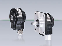
Hubner Berlin AHE7
Compact Incremental Encoders (Digital-Tachos) in die-cast aluminum housing with a hollow shaft or flange mount for monitoring speed or position in drive systems, especially for AC motors

- 60 to 10,000 ppr
- 120kHz switching frequency
- supply voltages: +9…+26V, HTL +5V, TTL
Click here for the General Data Sheet
Click here for the AHE7 Installation and Operating Instructions
HÜBNER / SIEI America Incremental Encoders (Digital-Tachos) have over the years become standard in many areas of industry due to their rugged construction adapted to the application
(HeavyDuty Technology):
- Sensing by opto-ASIC, compensated for temperature and aging
- EMC in compliance with CE regulations
- High vibration and shock resistance in accordance with IEC 60068-2-6 and IEC 60068-2-27
- 2 years warranty within the conditions of the German Electrical Manufacturer’s Association (ZVEI)
- ISO 9001 certified
Features:
- Compact aluminium housing
- Rugged incremental metal disk
- Servo flange and shaft 0.375”: AFE 7
- Hollow shaft max. 0.55” (0,5” stock): AHE 7
- Internal terminal strip
- Logic level TTL (RS-422) or logic level HTL (version C with line driver IC)
- Protection IP 56
Award for good Industrial Design iF 1995
Important Notes:
- Incremental Encoders are opto-electronic precision speed measurement devices which must be handled by skilled personnel and with care during transportation, mounting and operation.
- The Incremental Encoder AFE 7 with solid shaft is driven via a torsionally stiff, flexible coupling (e.g. Hübner spring disk coupling K35) which should be slid onto the shaft with minimum axial pressure. If shaft eddy currents occur in the motor shaft, it is recommended to use an insulated coupling like the Hübner spring disk coupling K 35 with insulated hub.Hammering the coupling on the shaft is not permitted because the
ball bearings may be damaged. - The Incremental Encoder AHE 7 with hollow shaft must be installed to the motor shaft without pressure to avoid a damage of the ball bearings.
- The devices are manufactured according to quality standard DIN ISO 9001. EU Declaration of Conformity meeting Council Directive 89/336/EEC art. 10 and annex 1 (EMC Directive).
- Do not connect outputs to supply voltage:
!!! Danger of Damage !!!
Please, pay attention to possible voltage drop in long cable leads (input and output). - Shielded cables should be used with twisted lead pairs. If possible, they should be placed uninterrupted and seperately, but at a clear distance from the motor cables. Normally the cable shield is connected to a large surface on the housing via a cable screw or an earth clamp. Cable terminating resistance 120 Ω for TTL and sinewave.
- The expected operating life of the devices is governed by the ball bearings, which are manufactured with a permanent lubrication to give approx. 20,000 operating hours (≥ 109revolutions).
